
This article was updated in June 20, 2026 with new products and information by Mark S. Taylor
The exact millisecond your dashboard ABS (Anti-lock Braking System) warning light illuminates, your vehicle’s computer safely disables emergency brake modulation. If you are forced to slam on your brakes during a sudden downpour or over a patch of black ice, your wheels will instantly lock up, causing the vehicle to skid uncontrollably and eliminating your ability to steer clear of an obstacle.
The primary trigger for a disabled braking loop is a malfunctioning wheel speed sensor. These sensors live in the harshest environment on the vehicle—suspended directly on the spinning wheel hubs where they are continuously hammered by brake soot, road salt, extreme thermal cycles, and heavy chassis vibrations.
As an ASE-Certified Master Technician, I have seen hundreds of drivers blindly purchase expensive new ABS control modules when the actual fault was a $30 wheel sensor caked in metallic brake dust. In this comprehensive guide, we will break down the structural electronics of Active vs. Passive sensors, the critical diagnostic symptoms, and how to execute a professional millimeter check without frying your car’s computer.
Contents
- 1 What Is an ABS Sensor and Why Does It Fail?
- 2 Know Your System: Active vs. Passive ABS Sensors
- 3 Active vs. Passive ABS Sensor Comparison Matrix
- 4 Tools You’ll Need
- 5 How to Test an ABS Sensor: Step-by-Step
- 6 Interpreting Your Results: The Diagnostic Flowchart
- 7 Can You Drive With a Bad ABS Sensor?
- 8 Repair Cost Breakdown
- 9 FAQs How to Test ABS Sensor
- 10 Verdict: Test It Yourself Before You Pay the Shop
What Is an ABS Sensor and Why Does It Fail?
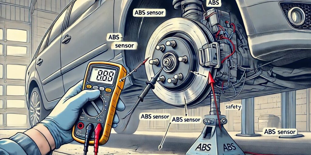
An ABS wheel speed sensor is a magnetic pickup that sits near a toothed metal ring — called a reluctor ring or tone ring — on your wheel hub, CV joint, or axle. As the wheel spins, the teeth pass the sensor. The sensor converts that motion into an electrical signal that tells the ABS module how fast each wheel is turning.
The ABS module compares all four wheel speeds in real time. If one wheel is about to lock up during braking, the module pulses the brake pressure to that wheel. Without accurate sensor data, the whole system goes blind.
Sensors fail for a few reasons:
- Corrosion and moisture — the connector gets wet, pins oxidize, signal degrades
- Physical damage — road debris, potholes, or careless brake work cracks the sensor
- Heat damage — brake rotor heat cooks the sensor over time
- Rust under the sensor — a tiny layer of rust lifts the sensor, changing the air gap between the sensor tip and the tone ring
- Wiring chafing — the harness rubs against suspension parts and shorts or opens
The sensor doesn’t just read wheel speed — it reads the gap between itself and the tone ring. A little rust under the sensor can change that gap and throw the same code as a dead sensor. That’s why testing matters — you might clean and reinstall the old sensor instead of buying a new one.
Know Your System: Active vs. Passive ABS Sensors
You must identify your vehicle’s specific sensor architecture before grabbing a diagnostic meter. Testing an ABS sensor using the wrong electrical setting can permanently burn out its internal micro-electronics.
1. Passive ABS Sensors (Two-Wire Magnetic Reluctance)
Typically found on vehicles manufactured before 2010. These sensors utilize an internal copper coil wrapped tightly around a permanent magnet. As the vehicle’s steel tooth tone ring spins past the magnetic tip, it naturally generates its own alternating current (AC Voltage).
- The Diagnostic Trait: Because this is a passive magnetic coil, it can be safely tested for electrical resistance (Ohms).
2. Active ABS Sensors (Two-Wire or Three-Wire Hall Effect)
Found on 95% of modern vehicles built in the last decade. These sensors contain integrated electronic circuit chips (IC) that require a steady 5V to 12V reference voltage feed from the main ABS control module to function. As a magnetic encoder ring spins past, the sensor clips the voltage into a digital square-wave signal.
- ⚠️ Critical Warning against Ohm Testing: Never attempt to measure the resistance (Ohms) of an Active ABS sensor. Sending the multimeter’s internal testing current backward into an active Hall-effect integrated circuit chip will instantly fry the micro-electronics, permanently destroying a perfectly good sensor. Active sensors must exclusively be evaluated using a DC Voltage sweep or a live data scan tool.
Active vs. Passive ABS Sensor Comparison Matrix
| Technical Feature | Passive ABS Sensor | Active ABS Sensor |
| Wire Count | 2 Wires | 2 or 3 Wires |
| Power Source | Self-generating (Internal Magnet) | Requires 5V to 12V reference from ABS module |
| Output Signal Type | Analog AC Voltage (Sine Wave) | Digital Square Wave (DC Voltage) |
| Safe Resistance Test | ✅ Yes ($800\ \Omega \text{ to } 2,500\ \Omega$) | ❌ NO! (Will destroy internal IC chip) |
| Wheel Spin Test Setting | AC Volts (Millivolts scale) | DC Volts (Pulsing state transitions) |
| Common Vehicle Eras | Pre-2010 Models | Modern 2010+ Vehicles |
Tools You’ll Need
- Digital multimeter — must read DC volts, AC volts, and ohms. AC millivolts capability is essential for passive sensor testing. A $20 unit from the auto parts store works fine.
- OBD-II scanner — to read the specific code and confirm which wheel is flagged. Borrow one free from most parts stores.
- Back-probe pins or paper clips — to access connector terminals without damaging them
- Service manual or wiring diagram — for your specific vehicle’s resistance spec and pinout
- Jack and jack stands — only if the cabin harness access doesn’t work for your vehicle
- Flashlight — to inspect the sensor and tone ring

How to Test an ABS Sensor: Step-by-Step
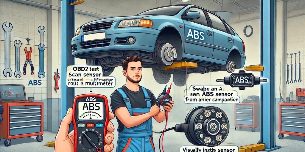
Step 1: Read the code first. Plug in the OBD-II scanner and note which sensor is flagged — front left, front right, rear left, or rear right. Don’t guess. The code tells you exactly where to look.
Step 2: Try the cabin-access shortcut. Most vehicles have ABS sensor harness connectors inside the cabin. For front sensors, check near the inner strut towers in the engine bay — the wiring usually passes through the firewall here. For rear sensors, look under the rear seat cushion or inside the trunk near the side panels. If you can reach the connector here, you don’t need to jack up the car.
Step 3: Disconnect the sensor connector. Whether at the cabin access point or at the sensor itself, disconnect the connector so you’re testing the sensor alone — not the wiring or the ABS module.
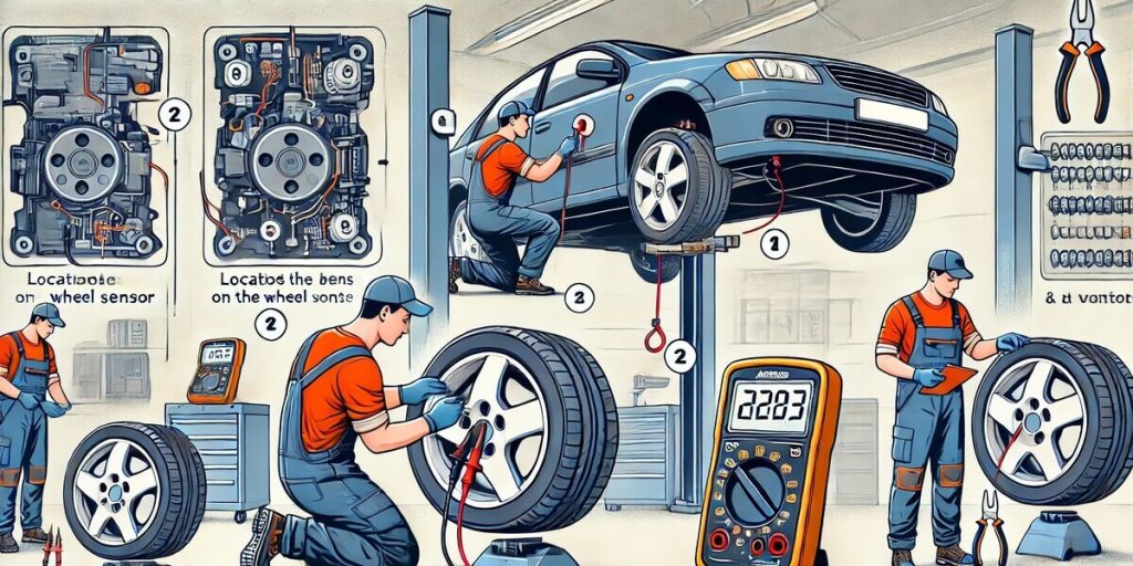
Step 4: Test resistance (both sensor types). Set your multimeter to ohms. Touch the probes to the two terminals in the sensor side of the connector (not the wiring side).
- Passive sensor: Expect 800–2,500 ohms. A steady reading in this range means the coil is intact. If you get an open (infinite resistance), the coil is broken. If you get a short (near zero ohms), the winding is internally shorted.
- Active sensor: Expect 1,000–2,500 ohms, but check your service manual — active sensors vary more by manufacturer. Some read as low as 700 ohms.
⚠️ SAFETY: If the resistance reading jumps around or steadily climbs while you’re holding the probes, the sensor is faulty. A good sensor gives a stable reading.
Step 5: Test for shorts to ground (both types). Move one multimeter probe to a good ground (battery negative or bare metal frame). Leave the other probe on each sensor terminal, one at a time. You should see infinite resistance (open circuit) on both terminals. Any reading to ground means the sensor insulation is compromised — replace it.
Step 6: Test AC voltage output (passive sensors only). Reconnect the sensor to the wiring harness. Set the multimeter to AC volts (millivolts range). Touch the probes to the two sensor wires. Spin the wheel by hand at about one revolution per second. You should see 0.1 to 1.0 volt AC. The faster you spin, the higher the voltage. No voltage means the magnetic pickup isn’t generating a signal — replace the sensor.
Step 7: Test DC voltage output (active sensors only). With the ignition on and the sensor connected, back-probe the signal wire with your multimeter set to DC volts. Spin the wheel by hand. The voltage should toggle between low and high states as the tone ring teeth pass the sensor. If voltage stays fixed while the wheel spins, the sensor isn’t switching — replace it.
Step 8: Inspect the sensor and tone ring (if accessible). If your tests are inconclusive or you suspect physical damage, jack up the car and remove the wheel. Look for:
- Cracks in the sensor body
- Corrosion on the connector pins
- Metal debris stuck to the sensor tip
- Rust buildup under the sensor mounting surface
- Missing or damaged teeth on the tone ring
- Excessive air gap between sensor and tone ring
Clean rust and debris with a wire brush. If the tone ring teeth are damaged, the sensor will never read correctly — replace the tone ring or hub assembly.
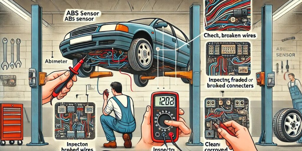
Step 9: Test the wiring harness (if sensor tests good). If the sensor passes resistance and voltage tests but the code persists, the problem is in the wiring or the ABS module. With the sensor disconnected, check for reference voltage at the wiring harness connector (active sensors only — should be 5–12V with ignition on). Check continuity from the harness connector to the ABS module. A break in the wiring between the sensor and the module is common, especially where the harness flexes near the suspension.
Interpreting Your Results: The Diagnostic Flowchart
| Test Result | What It Means | Next Step |
|---|---|---|
| Resistance: open (infinite) | Broken coil inside sensor | Replace sensor |
| Resistance: short (near zero) | Internal winding shorted | Replace sensor |
| Resistance: erratic/jumping | Intermittent internal fault | Replace sensor |
| Resistance: good, AC voltage: none (passive) | Magnetic pickup weak or tone ring damaged | Inspect tone ring, replace sensor if ring is good |
| Resistance: good, DC voltage: fixed (active) | Hall element not switching | Replace sensor |
| Resistance: good, voltage: good, code still present | Wiring fault or ABS module issue | Test harness continuity, check connectors |
| Resistance: good, voltage: good, no code after clearing | Intermittent connection or debris | Clean and reinstall, monitor |
If resistance is good but voltage is bad, the sensor is mechanically damaged — cracked housing, wrong air gap, or internal moisture — but electrically intact. Replace it. If both resistance and voltage are good, the problem is in the wiring or the ABS module. Don’t buy a sensor you don’t need.
Can You Drive With a Bad ABS Sensor?
Your base brakes still work fine. The pedal feels normal for normal stopping. But here’s the problem: in a panic stop on wet pavement, snow, or gravel, your wheels can lock up. Without the ABS module getting accurate speed data from all four wheels, it can’t pulse the brakes to prevent lockup. You’ll slide just like cars from the 1980s.
⚠️ SAFETY: A bad ABS sensor also disables traction control and stability control on most vehicles. In a sudden swerve on a slick road, you have no electronic help. The car can spin out. If you live where it rains or snows, fix this within a few days. In dry climates, you can stretch it a week or two — but don’t ignore it.
When in doubt, have a professional inspect it.
Repair Cost Breakdown
| Repair | Parts | Labor | Total | Notes |
|---|---|---|---|---|
| DIY sensor replacement | \$15–\$80 | \$0 | \$15–\$80 | 30 min–1 hour; one bolt and a connector |
| Independent shop | \$15–\$80 | \$100–\$200 | \$115–\$280 | 1–1.5 hours labor |
| Dealer | \$50–\$200 (OEM) | \$150–\$400 | \$200–\$600 | Includes diagnostic fee |
| Wiring harness repair | \$20–\$50 | \$100–\$250 | \$120–\$300 | If harness is damaged, not sensor |
| ABS module replacement | \$300–\$800 | \$200–\$400 | \$500–\$1,200 | Rare; test everything else first |
The sensor itself is $15–$80. The $600 dealer quotes are almost entirely labor — and on some cars, the sensor is just a single bolt behind the wheel. I’ve replaced sensors in 15 minutes on a lift. The markup is real.
FAQs How to Test ABS Sensor
What are the symptoms of a bad ABS sensor?
The ABS warning light is the first sign. You may also see the traction control light or stability control light. The brake pedal might pulsate during normal braking on dry pavement. The speedometer can read erratically or stop working on some vehicles. In hard braking, the wheels may lock up and skid. The car might pull to one side when braking.
Can I drive with a bad ABS sensor?
You can, but you shouldn’t for long. Your base brakes work normally for everyday driving. But ABS, traction control, and stability control are disabled. In a panic stop on wet or slippery roads, your wheels can lock up and you’ll lose steering control. In dry climates, you have a few days. In rain or snow country, fix it within a week.
How much does it cost to replace an ABS sensor?
DIY: $15–$80 for the part. Independent shop: $115–$280 including labor. Dealer: $200–$600. The wide range depends on whether the sensor is a simple bolt-on or integrated into the wheel hub assembly. Some vehicles require hub replacement to get the sensor, which jumps the cost to $400–$800.
What’s the difference between a passive and active ABS sensor?
Passive sensors (2-wire, older cars) generate their own AC voltage using a magnet and coil. Active sensors (2 or 3-wire, modern cars) are Hall-effect sensors that need reference voltage from the ABS module and output a digital square wave. You can’t tell by looking — check your service manual or test for reference voltage at the connector with the ignition on.
Do I need a scan tool or can I test with just a multimeter?
You can test with just a multimeter if you know which sensor type you have. A scanner helps identify which wheel is flagged and confirms the code clears after repair. Most auto parts stores lend scanners free. For the actual sensor testing, a multimeter is all you need — but it must read AC millivolts for passive sensors.
Verdict: Test It Yourself Before You Pay the Shop
If you can read a multimeter and follow a flowchart, test the ABS sensor yourself. The whole diagnosis takes 15–30 minutes and costs nothing if you borrow the scanner. You’ll know for sure whether the sensor is bad, the wiring is damaged, or the problem is deeper in the ABS module.
If the test is inconclusive or you find wiring damage inside the harness, pay the $100 diagnostic fee at a shop. It’s cheaper than guessing wrong and buying a sensor you don’t need — or worse, replacing a good sensor while the real problem is a chafed wire 18 inches away. When in doubt, have a professional inspect it.